Reusable Launch Vehicle Technology
KST’s Patented Tow Launch System Design Heritage
The basic concept of towing an un-powered aircraft behind a powered aircraft and then releasing it for autonomous flight was first demonstrated over 60 years ago. Extremely heavy tow operations were accomplished with the German ME321 transport glider. This aircraft had a wingspan of 178 feet, a length of 91 feet and a takeoff weight of 75,000 lbs. The United States developed a successful glider version of the C-47 (DC-3). In addition, the U.S. Air Force demonstrated long distance cross-country towing of the F-80 fighter plane with a B-29 bomber.
Early Development History
KST’s initial “Eclipse” tow launch system (Mid 1993) called for a fully expendable, unmanned, air launched booster using all solid propellant motors. Trade studies showed that a reusable, manned, liquid–fueled first stage with an expendable upper stage is significantly more economical than a completely disposable booster. The reusable first stage “ Sprint,” “Express” and “ Astroliner” vehicle configurations have undergone significant evolutionary upg rades over the last several years as the design s matured and new market applications have emerged. The original design of the Astroliner was unmanned. The current configuration is manned with a two-pilot flight crew. The rationale for inclusion of pilots i s two-fold. First, it is easier to make the vehicle compatible with normal airspace operations, i.e. just another aircraft. Typically, unmanned aircraft are limited to restricted military special use airspace or to extremely limited prescribed routes that require chase aircraft at all times. For example, NASA Dryden Flight Research Center ( DFRC ) personnel strongly recommended that the Astroliner be manned based upon their difficulties in setting up the flight test program for the X-33/X-34. Second, a manned aircraft provides a level of control system functionality and reliability, from first flight, that could not be obtained at reasonable cost in time and dollars any other way. NASA ’s Ames Research Center performed an independent assessment of the Astroline r concept simulating take-off and tow launch. The subsonic aerodynamics of the Astroliner were modeled using an engineering Computational Fluid Dynamics (CFD) code to generate lift, drag, and moment coefficients. This work verified analyses performed by KS T with the following conclusions:
• Towed take-off of the Astroliner launch vehicle in this configuration is feasible
• The additional runway length required for a towed takeoff compared to the 747 alone is less than 1,000 feet.
• The 747 is capable of towing the Astroliner to between 25,000 and 40,000 feet.
KST and TRW also performed trajectory simulations for the Astroliner ascent reentry profiles. NASA’s Dryden Flight Research Center then performed an independent assessment of the Astroliner re-entry trajectory using a simulator developed for the National AeroSpace Plane (NASP) program. These analyses confirmed the viability of the Astroliner design approach.
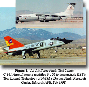
KST demonstrated its patented Eclipse Tow Launch Technology in a series of six successful flight tests, which ran from December 1997 through February 1998, at NASA’s Dryden Flight Research Center (DFRC) at Edwards Air Force Base, California(See Figure 1). The Tow Launch demonstration flights were conducted by KST, in cooperation with NASA Dryden Flight Research Center and the Air Force Flight Test Center under a Small Business Innovation Research (SBIR) contract awarded by the Air Force Research Laboratory (AFRL), formerly the USAF Phillips Laboratory.
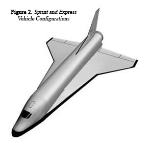
The KST “ Eclipse ” development program was d esigned to progress from the QF-106 demonstrator to the full sized Astroliner in carefully considered incremental steps: Sprint, Express ( shown in Figure 2 ) and the Astroliner vehicle configurations briefly described below.
Figure 2. Sprint and Express Vehicle Configurations
Sprint Vehicle
Reusable sounding rocket, Mach 6 Flight, tow-launched
Subscale version of Eclipse Astroliner vehicle, no upper stages
Address smaller half of $77 million/year market immediately
Express Vehicle
Eclipse Sprint vehicle with upper stages
Ejects upper stages with payload like Astroliner
Addresses large sounding rocket and small satellite market.
System Description
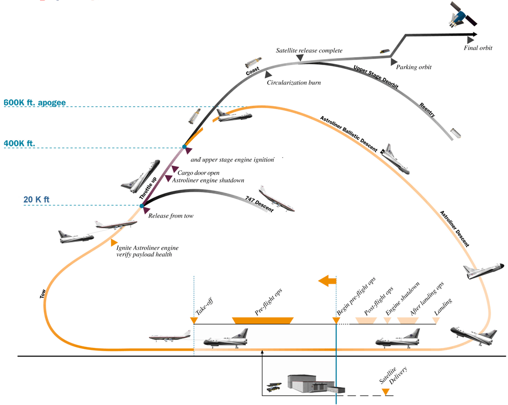
The two-stage-to-orbit Astroliner launch system consists of a piloted, winged, rocket-powered, liquid-fueled aerospace plane with an internally-stored upp er stage and payload. A Boeing 747 aircraft is used to tow the Astroliner aerospace plane from a conventional runway to the desired “launch site . ” During and throughout the climb to the launch site, the Astroliner’s jet engines are operating, providing a n added element of operating safety and increasing the amount of cargo mass it can deliver to orbit. Upon reaching the intended launch site, operation of the turbine engines is discontinued, its reusable rocket engines are ignited and the towline is relea sed. The B-747 tow aircraft begins its return to the landing destination while the Astroliner ascends to an altitude of approximately 600,000 feet. As the Astroliner passes through an altitude of 300,000 feet, its rocket engines have completed their task and are shut down. At 400,000 feet, after leaving the detectable atmosphere, the Astroliner’s cargo nose door is opened, allowing precisely controlled ejection of its payload and an expendable orbit-insertion upper stage from the Astroliner’s internal ca rgo bay. When at a safe distance from the Astroliner, the upper stage is ignited to deliver the payload to its specified destination. Meanwhile, the Astroliner nose door is closed and the aerospace plane begins its re-entry into the atmosphere and descen ds.
Figure 3. Typical Astroliner Flight Profile Click on image to zoom in.
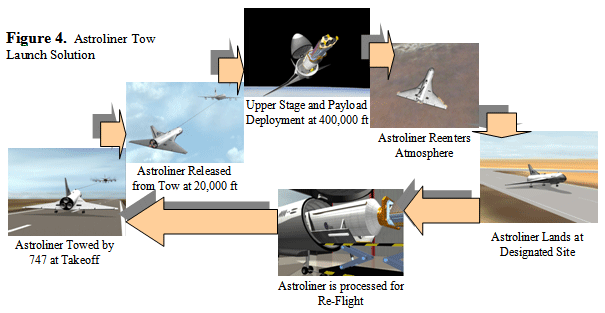
To facilitate a powered final descent and landing, at approximately 30,000 feet, the pilots restart the Astroliner’s turbojet engines and fly it like any other transport class aircraft to its destination airport and final landing. Sufficient fuel is budgeted to allow the pilots to fly the Astroliner an additional 500 miles to a destination other than its point of takeoff. The Astroliner is then inspected, refurbished and readied for its next flight (See Figures 3, 4 and 5 ).
Design Overview
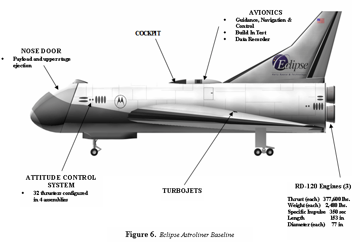
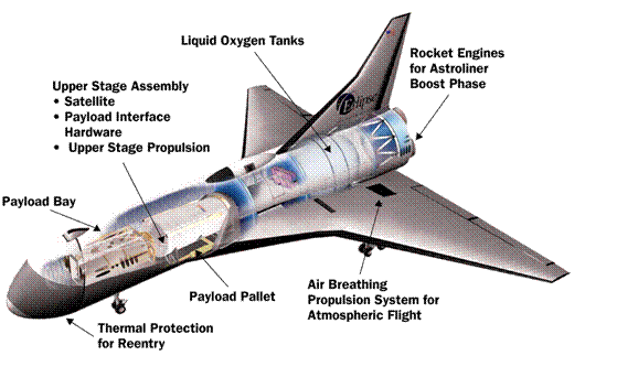
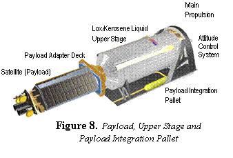
The manned Astroliner recoverable launch vehicle consists of the airframe, primary propulsion system, Attitude Control System (ACS), Air-Breathing Propulsion System (APS), Thermal Protection Systems (TPS), Avionics systems (including software), and crew accommodations. The Astroliner has a double delta wing, a single vertical stabilizer, and an airframe of conventional semi-monocoque aluminum construction (Figures 6 and 7). A large payload bay carries the upper stages and payloads. To deploy the upper stages and payload, an articulated nose assembly swings open. Installation and deployment of the integrated upper stage assembly and payload is through this same door. Located behind the payload bay is the avionics bay and access to the crew compartment. The crew compartment itself is located in the upper portion of the fuselage above the avionics bay. The primary propulsion system is located behind the avionics bay at the rear of the fuselage. This is a cluster of three RD-120 liquid kerosene/ liquid oxygen rocket engines with a combined thrust of 1,132,800 lbs. The three engines are mounted in a Line Replaceable Unit (LRU) to allow rapid change-out and return of the Astroliner to service and off-line servicing of the engines. The wing-mounted aerodynamic control surfaces are large elevons that extend across the trailing edges of the wing. The vertical stabilizer is equipped with a split rudder that also serves as a drag brake. The Astroliner landing gear is a hydraulically operated tricycle configuration and has a rejected takeoff braking capacity that is sufficient to safely stop a fully loaded Astroliner. The Astroliner has a payload bay that accommodates varied mission requirements through the use of specialized integration pallets (Figure 8) with standard interfaces. These pallets are designed to meet all payload thermal conditioning and interface requirements and have self-contained environmental isolation and control systems. Pallet connections to the Astroliner payload bay are mechanical tie-downs and data and power connectors. For all satellite launches, the payload pallet will also support the upper stage required for the orbital injection phases of the launch and the Payload Adapter Deck that provides the mechanical interface to the Space Vehicle.
Stage 1
Figure 7. Cutaway of Astroliner Launch Vehicle
Stage 1 of the Astroliner launch system is a fully reusable winged, rocket-powered aerospace plane. The Shuttle-sized Astroliner Stage 1 vehicle weighs approximately 708,000 pounds on takeoff when fully loaded with its payload-orbit inserti on stage combination and all propellants on board to perform the space launch mission. Its landing weight is approximately 194,000 lbs. It carries approximately 73,000 lbs. of gross cargo weight (including the upper stage) in the payload bay. It carries approximately 320,000 pounds of oxidizer (liquid oxygen) and 123,000 pounds of fuel (kerosene). The kerosene is consumed by the three reusable RD-120 rocket engines, and the F-414 jet turbine engines. The overall length of the Astroliner is 121 feet wit h a wingspan of 140 feet and a tail height of 60 feet. The pressurized crew compartment is designed to carry two pilots and a mission observer. The cargo bay is 18 feet in diameter (dynamically) and 45 feet in length, not including the added length forwa rd of the nose door hinge point.
Stage 2
The Astroliner first stage is designed to take satellites and cargoes to sub-orbital altitudes and velocities. The remaining orbital delivery task is performed using an expendable liquid oxygen/kerosene upper stage. The upper stage has an inert weight of approximately 4,800 pounds with 58,000 pounds of propellant, and supports delivery of spacecraft weighing in excess of 10,000 pounds. After delivering the payload to the desired destination, the upper stage is detached from the satellite and de-orbited. Future options will include designing this stage to be recoverable and reusable. For lighter payload missions, upper stage configurations may include commercially available expendable solid propellant boosters.
The primary interface between the payload and the Astroliner launch system is the Payload Adapter Deck. It supports the payload and the electrical interface equipment and provides the payload attachment to the upper stage. The baseline Payload Adapter Deck attachment system is a set of pyrotechnically actuated fasteners combined with a set of separation springs. The pyrotechnic fasteners do not generate any fragmentation, high velocity particles, or combustion products. Alternatively, accommodations can be made for mounting and actuation of customer-specified V-band rings. The upper stage assembly is mounted on the Payload Integration Pallet that is carried in the Astroliner payload bay. The payload integration pallet is equipped with a self-contained environmental isolation and control system, data collection systems, and power regulation systems that are readily adapted to accommodate changes in customer needs. Pallet connections to the Astroliner payload bay consist of rails by which the pallet is loaded into the Astroliner, a deployment actuator, and data and power connections. The payload integration pallet remains in the Astroliner after payload/upper stage separation.
Payload Processing
The Space Vehicles (SVs) are transported from the customer’s facility to the launch airport in environmentally controlled shipping containers. Once at the airport, the containers offloaded and placed into the Payload Integration Facility receiving lock. After the receiving air lock has been sealed and cleaned, the inner lock door into the Class 100,000 integration area is opened and the SV on its shipping cradle is removed from its shipping crate. This shipping cradle is then attached to the SV handling dolly. At this point, The SV manufacturer performs receiving inspection. SV fueling operations begin by moving the SV fuel shipping container into the fueling enclosure. The SV on its dolly is then moved into the fueling enclosure. The fueling enclosure doors are closed and their seals verified. The fuel is then transferred from the shipping container to the SV. After fueling is complete, the enclosure environment is verified personnel safety and the doors are re-opened. The SV on its dolly is then removed from the enclosure and brought back into the clean integration area. Battery loading operations begin by rotating the SV on its shipping cradle to vertical as required. The batteries are then loaded. Portable monitoring equipment is available to verify SV systems as needed. After successful battery loading and checkout, the SV is then rotated back to horizontal. SV integration with the Payload Accommodation System now begins. With the SV still on its handling dolly, the SV interface plate is aligned with the SV interfaces, the electrical connector is mated, and the pyrotechnic attachment fittings are installed. At this stage, the leads from these fittings are left unconnected to ensure personnel safety. The SV release springs are then installed. Next, the SV handling dolly is rolled to the PAD and is raised into position and aligned. The SV interface plates are bolted to the PAD and the SV MEU is connected to the upper stage avionics. Directed cooling air flow ducts to provide SV battery cooling are then installed. An integrated system checkout is per-formed using the portable monitoring equipment attached to the pallet-to-Astroliner connector. Transponder signals are also verified.
SV Encapsulation and Pallet Storage
When the customer is satisfied that the SV is ready for flight, the pallet is closed out. The first step is to attach the SV pyrotechnic attachment fitting leads to the upper stage avionics. At this point the SV ground processing environmental shroud is attached to the front end of the pallet around the SV(s). The pallet environmental control system (ECS) is then activated and the SV environment is verified. The encapsulated pallet is pulled back into the general integration area of the PIF to await mating with the Astroliner. Power from the PIF to the pallet and full SV environmental control is maintained during this storage period.
Pallet Integration with the Astroliner
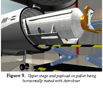
On flight day, the upper stage helium tanks and pallet ECS nitrogen tanks are loaded. The pallet transport vehicle then moves the integrated pallet to the open payload bay of the Astroli ner and aligns the pallet with the support rails in the payload bay ( Figure 9 ). The pallet is rolled into the payload bay and connected to the pallet positioning actuator. This actuator completes the pallet installation into the payload bay. The pallet-to- Astroliner connectors are then mated and the PIF power lead is disconnected. Power to the pallet subsystems is now provided through the Astroliner. The portable monitoring equipment is connected to the Astroliner external umbilical panel and a full system checkout is performed. At successful completion, the Astroliner nose door is closed. The Astroliner is now ready for propellant loading and flight. The Launch Readiness Review is then conducted. The Astroliner is pulled out of the hangar and towed to the p ropellant loading area. After all propellants are loaded, a Flight Readiness Review (FRR) is conducted. This FRR consists of a “go/ no-go” poll using the first set of launch commit criteria of the subsystem representatives onboard the 747 as well as the gr ound handling crew at the fueling field.
Flight Operations
After the FRR is completed, the 747 and Astroliner is towed aloft to the ascent transfer point. After successfully satisfying the second set of Launch Commit Criteria , the Astroliner main engin e is ignited at a 70% throttle level and verified. The tow cable is released and the Astroliner throttles up and begins its ascent through the atmosphere. If any problems are detected during engine ignition, the launch can be aborted and the Astroliner tow ed back to the integ ration field with the SV intact. During normal operations, the Astroliner ascends with telemetry monitoring maintained by the payload monitoring crew on the 747. Also, the Astroliner flight crew will monitor the SV health. As the 400,00 0-foot release point is approached, the launch countdown is conducted in accordance with the Integrated Launch Commit Criteria. If the launch is a no-go, the Astroliner nose door will not be opened and the SV is returned safely to the integration facility. During normal “go” operations, the Astroliner nose door is opened, the pallet is moved forward and the upper stage is released from the payload bay. The upper stage momentum will carry it forward and cleanly away from the Astroliner. The upper stage attit ude control thrusters are then fired to align the upper stage with the proper flight path and to perform a propellant settling burn. The upper stage engine is then ignited. Once orbit is reached, the upper stage avionics will fire the SV pyrotechnic attach ment fittings and the SV will be deployed. After sufficient clearance is achieved, the upper stage engine will perform a de-orbit burn.
Facility and Range Provisions, Operating Base Facilities
Because the Astroliner launch vehicle is an air launched system, it need not be based at government flight test range facilities as are the existing launch vehicles. Also, the requirement for range facilities is significantly reduced. The main support facilities for the Astroliner and its payloads will be located at San Bernardino International Airport and will not be shared with other users.
Environmental Impact
The Astroliner Launch System design minimizes environmental assessment requirements in at least two ways. Since the Astroliner system uses existing airports and does not require new construction of any major ground or range facilities, a large scale federal Environment Impact Statement (EIS) will not be required. The required ground facility for the Astroliner system is no more than a large hangar. In addition, the propellants for the Astroliner are non-toxic, i.e. LOx, kerosene, propane, and nitrous oxide. The most significant hazardous material concern for the Astroliner system is the hydrazine thruster fuel sometimes required for the SVs.
Fueling Facilities
The Astroliner Ground Support Equipment at the operating base includes the propellant loading systems for the SV, Astroliner, upper stage and the 747 tow aircraft. Tow aircraft operations require conventional jet aircraft fueling and maintenance facilities. The Astroliner requires propellant loading facilities for RP-1 and liquid oxygen for the main propulsion system, and upper stage, JP-8 for the air-breathing propulsion system and propane and nitrous oxide for the attitude control system.
Astroliner/Payload Integration Pallet
• RP-1
• Liquid Oxygen
• ACS Nitrous Oxide
• ACS Propane
• Gaseous Helium
• Gaseous Nitrogen
• Liquid Nitrogen
Upper Stage
• RP-1
• Liquid Oxygen
• Gaseous Helium
• ACS Nitrous Oxide
• ACS Propane
Electronic Test Equipment
The electronic test equipment for the Astroliner and its upper stages consists of a mobile suite of dedicated equipment that is located at the operations hangar. Sufficient spares will be in place on site to ensure that rapid repair of the test equipment can be performed to avoid any operational impacts. The test equipment, when used in conjunction with the self diagnostic capabilities of the Astroliner airborne equipment provides systems test and fault isolation to the Line Replaceable Unit level. Sufficient spares will be kept on location to ensure the capability to rapidly bring the system back to an operational condition.
Upper Stage and Avionics Storage Area
KST will maintain a facility for the storage of avionics components and upper stages. This facility will be climate-controlled and secure, with bonded storage areas that are access-controlled.
Battery Preparation Area
This facility is the location for the preparation of primary batteries for the upper stage and SV. This facility provides temperature-controlled storage (70±5°F (21±3°C)) for batteries and the battery chemicals. It also provides facilities for the disposal of electrolyte solutions.
Payload Integration Facility (PIF) at the Operating Base
The payload processing facility contains all payload processing functions in a Class 100,000 clean room environment. The payload integration facility operates on commercial power, but has the capability to generate its own power for either emergency use or extended periods of operation. The facility has sufficient space to receive the SV and contain it and its handling equipment in addition to the Astroliner upper stage assembly, its components, and its handling equipment. The PIF is also equipped with a fire suppression system and facilities for clean up of toxic materials present at the site.
Airframe Maintenance Equipment at the Operating Base
Specific requirements for support facilities at the operating base include commercial electrical power, water, sewage, natural gas, and telephone. Astroliner launch operations also require use of land area for the tow aircraft operations (servicing and fueling), Astroliner servicing and propellant loading (including an area for liquid oxygen loading), upper stage processing and payload processing. Emergency services (fire and toxic spill clean up) are also required.
Flight Range Facilities
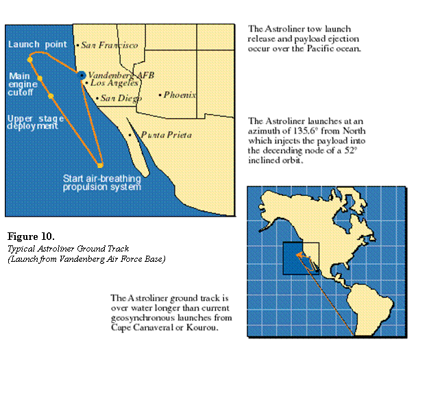
KST’s initial operational baseline is to perform SV missions out of Vandenberg Air Force Base (See Figure 10) and transition to inland operating bases as flight operations are demonstrated. Departure from Vandenberg will be over the Pacific Ocean on a northwesterly course to a point approximately 500 miles west of San Francisco. Over-flight of populated areas will be avoided. However, as system reliability is demonstrated, overland flight will be pursued, but for initial operations, KST has baselined Vandenberg Air Force Base. The flight will proceed over the Pacific Ocean to the launch point at an altitude of between 25,000 and 40,000 feet. The 747 then turns to the correct launch azimuth, the Astroliner main engines are ignited and the tow line is released. Main Engine Cut Off (MECO) occurs at 120 statute miles down range at which point staging occurs. The baseline ground track for a typical low-earth orbit mission launching from a point approximately 500 statute miles off the coast of California west of San Luis Obispo does not cross land until reaching the coast of Chile at a point south west of Santiago. This point is 5,000 miles from the upper stage ignition point and more than 4,300 miles after upper stage burnout. Therefore, for a payload to impact land would require a premature shut down of the upper stage during a short window that is more than halfway through the planned burn. This ground track is over water longer than current geo-synchronous launches from Cape Canaveral or Kourou. The Astroliner has the capability for approximately 550 statute miles of cross-range capability. During re-entry following the atmospheric skip, the Astroliner will turn to the northwest. By the time a point off San Diego is reached, the Astroliner will have decelerated to subsonic velocity and be operating as a conventional aircraft using its air-breathing engines. The flight path will then be directly back to Vandenberg. The final approach to landing will be to the east. Use of flight test range facilities will be limited to the Range Safety related functions and use of a runway for Astroliner landing. The system can also downlink guidance data to the range safety function for instantaneous impact prediction purposes. A console is reserved in the launch control center on the tow aircraft for a range safety representative. Voice communications with the range safety function are also available. The upper stage assembly of the Astroliner is equipped with a full compliment of range required flight safety equipment. After a normal launch mission, the Astroliner returns to the staging base under the power of its own air-breathing propulsion system (APS). The Astroliner enters the standard aircraft landing pattern, lands, taxis and is prepared for reflight.
