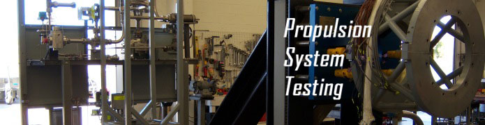
Jet & Rocket Engine Test Site
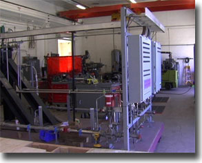
Kelly Space & Technology’s (KST) indoor rocket test facility cost-effectively supports research and development (R&D) and engine prototype testing on a commercial basis. The Jet & Rocket Engine Test Site (JRETS) West facility can test rocket engines over a thrust range of 75 – 20,000 lbf (88,964 N) thrust. The test facility can support rapid prototyping and development activities for rocket engines to enable small business as well as larger organizations to conduct cost-effective propulsion component, subsystem and system level testing for commercial and government applications.
The 18,000 square foot facility contains four separate test cells, two control rooms and two equipment rooms. Test Cells 1 and 2 are configured for rocket engine, systems and component testing. The test facility has supported (and is currently configured for) Liquid Oxygen and Liquid Methane propulsion systems. The facility can be modified to support LOX/LH2, LOX/RP and other engines using different propellant combinations. The facility is configured to use nitrogen or helium as the pressurization and purge gases; however, other options are possible. Larger propellant transfer and feed systems are located outside of the test facility and piped into the test cells. Smaller propellant systems may be installed in the test cells or directly onto the mobile test carts. Rocket engine feed systems within the cells are sized to meet specific test applications. Cell 3 is configured for either rocket or air-breathing systems and components. Cell 4 is configured for air-breathing engines and power plants.
Large gas storage vessels located outside the propulsion test facility for Air, GN 2 and GHe provide gas for direct connect testing of rocket system pressurization, purge and valve actuation. Small gas requirements are met with bottles or vessels located within the test cells. Test system can be pressurized using two each 200 gallon tanks, which can supply pressurization medium at 3,000 psi (tanks are carbon steel and are rated up to 5,000 psi)
High-pressure rocket propellant run-tanks are available in various sizes to support small attitude control systems, and engines up to 20,000 lbf thrust. Run tanks are selected to meet specific test requirements for run duration, flow-rate, pressure, and temperature. Larger tanks are located outside the propulsion test facility and smaller tanks are located in the test cells or on the test carts.
Our facility is configured to support a wide range of testing requirements through the use of mobile test carts. Mobile test carts provide the capability to assemble and build up test systems outside the test cells, while accommodating testing of other hardware within the test cells. In addition, each test cart is designed to facilitate a specific testing regime. Existing test carts are broken down into two different thrust classes: 0 – 3,000 lbf and 3,000 – 20,000 lbf thrust carts.
Special test equipment such as thrust measurement systems, thrust adaptors and cavitating venturis are provided as needed. Standard propellant and pressurizing components and piping are stocked to support build-up of the test systems. Each component is checked for compatibility and cleanliness before being installed into the propellant feed system. An inventory of standard transducers is maintained to support test systems. Specialized transducers are supplied by the user, or ordered, based on requirements. Standard and high speed video is available upon request.
Attributes of the JRETS West Facility
Each test cell has ample room for test article setup and test at 1,134 square feet. The maintenance bay has 3,690 square feet of work area that includes machine shop services.
Electrical power available in both the maintenance bay and test cell includes 120v single phase 100 amp, 120/208V 3 phase 100 amp, 240V 3 phase 200 amp, 480v 3 phase 200 amp, and 28 VDC 100 amp.
Test article cooling water is provided through a 2” supply rated at 42 psi with a flow rate of 300 gallons per minute. The drain water in the test cell is collected in a sump and pumped outside to a 3,000 gallon clarifier. This prevents any contaminates from entering the city water system.
Control Room “B” contains the Data Acquisition and Control (DAC) system and can comfortably house 8 people during testing. Safety cameras located throughout the Facility ensure that personnel are clear of the area during testing. A PA system and warning lights located throughout the building serve as an audio-visual warning system indicating the state of test operations.
Test System Description
Test Systems Capability
Test Carts are built up in the maintenance bay to satisfy the program’s interface requirements. This includes mounting of specifically designed adapter plates which are installed on the thrust measurement system and integrated to the carts. The carts are then rolled into the appropriate test cells and anchored to the floor with lugs and anchoring brackets. The cart system is integrated into the facility by completing mechanical and electrical connections. The facility and cart system is leak checked and cold flowed with liquid and or gaseous nitrogen depending on the propellants required by the test article. Test articles are then mounted on the cart for calibration, cold flows and hot firings.
0 – 3,000 lbf carts are outfitted with a thrust measurement system for up to 3,000 lbf of thrust and are designed to supply the test article with an inlet pressure of up to 3,000 psi. The carts contain on-board accumulators that provide thermal conditioning of propellants as desired. The design allows a quick reconfiguration for alternative propellants (for example: Oxygen – Methane, Oxygen – Kerosene). The orientation of the test article can also be pitched downwards for LOX/ Kerosene engines. A circuit for TEA/TEB ignition is already integrated into the cart systems to provide a wider range of ignition mechanisms. Propellant feed circuits are configured for staged flow conditions and can be easily modified to fit a wide range of testing requirements.
The 3,000 – 20,000 lbf carts are designed for test articles up to 20,000 lbf of thrust. These carts are designed with a thrust measurement system for up to 20,000 lbf of thrust and are nominally configured to supply the test article with propellant inlet pressures of up to 1,000 psi. A variety of run tanks are available to support various test configurations up to 20,000 lbf thrust. For short duration runs, tanks are mounted on the carts and for longer duration runs the larger run tanks are installed in the test cells or outside. Propellant run tanks are pressurized by either K-bottles in the test cells, or high capacity, high pressure vessels located outside adjacent to the Propulsion Test Facility.
The JRETS West facility’s pressurization and propellant feed systems are designed to provide flow rates supporting up to 20,000 lbf thrust. Chamber pressures up to 3,000 psia, depending on thrust and duration can be supported. Nominal chamber pressure up to 750 psia can be supported for the higher thrust levels up to 20,000 lbf of thrust.
Measurements and Instrumentation
Test systems include a high response thrust measurement system to 20,000 lbf. Thrust and flow measurements will be provided for fuel and oxidizer steady state and pulse performance testing.
Data Acquisition and Control System
Overview
The Data Acquisition and Control System is National Instruments hardware and software based Real Time acquisition and control system. The software was designed and written in-house, providing an expandable platform to accommodate varying customer requirements. In addition, the modular hardware base compliments the flexibility of the software by allowing for expansion by adding any of a number of specialized input-output devices. Quick look displays consisting of graphs are provided within one half hour from the end of test completion and the fully scaled ASCII (comma delimited) data package delivered within 24 hours from test completion.
Control System
The control system provides a flexible PC and National Instruments Real Time based platform for conducting multiple tests per day with varying I/O configurations. Key system features include:
I/O configurations can be saved and recalled for quick re-setup of a prior test
Test sequences are quickly programmable and can be simulated in software
Abort conditions are configurable (up to 15 channels) and have a 1 millisecond analog input to digital output response time
Test sequences have a time resolution of 1 millisecond
Watchdog timers provide an abort mechanism in the case of control system failure or automatic abort shutoff. The digital outputs in this case are configurable.
Input-Output Channel Summary
KST has a multitude of Data Acquisition and Control capabilities to offer from high channel count systems for rocket engine test to portable systems that can better accommodate smaller test setups. Below is an example of our I/O capabilities in Test Cell 2 designed for the testing of Rocket Engines. Sampling rates can be varied depending on testing requirements. Additional I/O channels can be added if greater channel counts are required.
128 digital input and output lines
56 16 bit strain gage inputs @ 1000 Hz, 0-10 V excitation, w/ programmable filter (10 Hz, 100 Hz, 1000 Hz, 1 kHz, or 10 kHz)
64 16 bit thermocouple, millivolt, volt, and current analog input lines @ 1000 Hz
8 24 bit analog inputs @ 32000 Hz , programmable IEPE signal conditioning
32 16 bit static analog outputs (16 ±10 V and 16 0 to 20 mA)
System Accuracy
The end to end worst case accuracy of the data acquisition system is below .5% FSO using a typical transducer and typically falls below .25% FSO with an end to end system calibration. Each transducer undergoes offset calibration prior to every test and is calibrated in place with NIST traceable calibration equipment to ensure the highest possible accuracy. NIST traceable calibration records on all applicable instrumentation can be provided in addition to an end to end system error analysis report.